.
Subscribe $20 per year
Subscriber Only

Assuming capacitor bank 1 is already switched on or energized.
Calculate the peak inrush current and resonant frequency that will flow through CB2 when capacitor bank 2 is switched on.
Reference: IEEE Std C37.012-2005 APPLICATION GUIDE FOR CAPACITANCE CURRENT
SWITCHING FOR AC HIGH VOLTAGE CIRCUIT BREKAERS
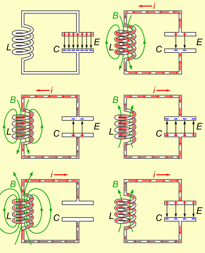
Back to back switching of series capacitor can generate high frequency transient peak current that can flow from already charged capacitor bank 1 through disconnect switch or circuit breaker going to capacitor bank 2 can be visualize using a tuned LC circuit shown below.
The animation speed was slowdown to 3 seconds for us to see the transient speed of high frequency inrush current. The actual speed of one (1) cycle of 2068 Hz resonant frequency is 1/2068 second or 0.483 milliseconds.

Credit to : Chetvorno from Wikimedia Commons
Step 1. Calculate the line reactance of cable, XL = ? Formula Memory Recall

|
Ω , line reactance of cable, XL
| = |
Ω * feet
feet
|
Step 2. Calculate the lumped inductance of cable, L = ? Formula Memory Recall

|
Henry, line inductance of cable, L
| = |
*
*
Hz
|
Step 3. Calculate the lumped reactance of capacitor bank 1, X C 1 = ? Formula Memory Recall

|
Ω , reactance of capacitor bank 1, X C 1
| = |
2 kV
MVAR
|
Step 4. Calculate the lumped capacitance of capacitor bank 1, C 1 = ? Formula Memory Recall

|
Farad , of each capacitor bank.
| = |
*
*
Hz *
Ω
|
Step 5. Calculate the equivalent capacitance of two series capacitor bank, C eq = ? Formula Memory Recall

When C1 = C2 it becomes

|
Farad; , C eq
| = |
Farad
|
Step 6. Calculate the resonant frequency of peak current, F res = ? Formula Memory Recall

|
Hz, F res
| = |
.
*
* √
H *
F;
|
Step 7. Calculate the surge impedance, Z o = ? Formula Memory Recall

|
Ω , Z o
| = |
√
H
√
F
|
Step 8. Calculate the peak currrent, I peak = ?
Formula Memory Recall
Pay attention the multiplier √ 2 is use assuming a sine waveform to quickly estimate the peak current. 0.8165 = √ 2 divided by √ 3

|
Amp , peak line current
| = |
* kV
Ω
|
The calculated peak current did not consider the system resistance and the inductance of the capacitors so it is always higher compare to power quality meter reading. The power quality meter like BMI/Electrotek is measuring the system resistance and the inductance of the capacitors. Hence the peak current reported by power quality meter is usually lower than the calculated peak current.
LinkedIn Shared Post about harmonic mitigation due to capacitor switching.
Formula and Calculator Index
Get command training data
IN-V-BAT-AI Never Forget
IN-V-BAT-AI search and compute faster.
IN-V-BAT-AI automating solved problem.
IN-V-BAT-AI automated intelligent (AI) assistant


