.
👈


📱 Launch 504 Custom Educational Websites for Just $30/Year
No coding. No hosting. Just results.
Empower your classroom, tutoring service, or educational platform with 200 custom calculators and 304 math exam tutor sites—all hosted and maintained for you. That’s 504 personalized tools for just 6 cents each per year.
✅ Zero technical setup
Just email us what you want updated—we’ll handle the rest.
✅ Instant deployment
Your tools go live fast, optimized for mobile and voice search.
✅ Built for learning
Designed to support memory recall, personalized study, and exam prep.
🎯 Who It’s For
Teachers who want ready-to-use digital tools
Tutors scaling their services without tech overhead
Students needing reliable, on-demand study aids
Anyone who believes learning should be accessible and affordable
Never forget. Always be ready.
With IN-V-BAT-AI, your knowledge lives in the cloud—ready when you are.

IN-V-BAT-AI solution to forgetting! No coding. No website hosting.
Remember on demand is now possible!

Using AI - Voice to Text Keyword, Phrases or Number Type here > tap SEARCH 2
Available Maximum Fault Current

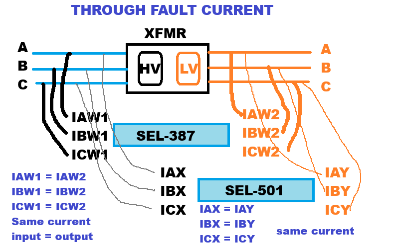
SEL-501 oscillography captures transformer through fault in milliseconds (60-70 ms) without sending trip command as back-up.
SEL-351S also record feeder faults.
Reference: Tarigma: Grid Enterprise Management (GEM) - waveform - Tarigma Event Viewer (TEV)
AH T3 failure
Studied by: Sam Ortega, Senior Engineer, SRP 3/31/2026
Disclaimer: The statements and opinions presented are the author’s alone and should not be interpreted as representing the official position, policies, or viewpoints of his employer.
Shown is a sample visualization of asymmetrical fault current in less than quarter (1/4) of a cycle.
Credit: Desmos Graphing
Calculate the base MVA maximum fault current using ANSI Method that would appear at the transformer bushing stud terminal. What is the base MVA internal winding fault current inside the tank on the high voltage coil or primary side of the transformer ? What is the 150 MVA internal winding fault current inside the tank? What is the 180 MVA internal winding fault current inside the tank? What is the 216 MVA emergency rating internal winding fault current inside the tank?
If the Digital Fault Recorder (DFR) Line to Ground Fault on Phase A recorded a fault of 3,850 A on the primary or high voltage side, did it exceed the emergency rating fault current? Explain your answer.


Given a 100 /150 / 180 MVA power transformer, 3 Phase 230/69 kV, delta-wye connection and has short circuit impedance of Z = 9.63%. The factory test report shows 100 MVA as the base MVA.
Next calculate the maximum fault current when this transformer is loaded at 150 MVA, 180 MVA and 216 MVA during emergency loading.

![]()
1 MVA = 1,000,000 VA ; 1 kV = 1000 V ; √3 = 1.732
Enter base MVA value and base kV value no need to do conversion. Answer is the base current in ampere.
|
Base current Line
Amp
| = |
3 Phase Base MVA
kV * 1.732
|
Go To Maximum Available Short Circuit Current
Section 7 of IEEE Std C57.12.00-2000 specified the general short circuit requirements for liquid-immerse distribution, power, and regulating transformers. For Category I and II transformers, symmetrical short circuit current shall be computed using transformer impedance only. For Category III and IV, system impedance should be included together with transformer impedance to calculate the symmetrical short circuit current. In our example our base MVA is 100 MVA, therefore it is a category IV transformer and should be calculated together with the system impedance. But for now we are neglecting the contribution of system impedance in our symmetrical short circuit calculation. By neglecting the system impedance, you are adding additional safety factor in your transformer short circuit withstand capability specification. In reality there is always the system impedance that will lower the calculated available short circuit current. But it is difficult to get the real time transmission line impedance value because the network is dynamic due to power flow changes, unplanned outages due to storm and planned outages for scheduled apparatus maintenance.


Link to Desmos: Simulation of Unbalanced AC Three Phase Systems
Is the zero sequence voltage, V0 the same as the unbalanced voltage in a three phase transmission line ? In a WYE - WYE transmission transformer , where is the transmission line neutral to carry the unbalance current driven by unbalance voltage?
Credit to: Desmos Graphing by Sam Ortega 3/7/2020
Phasor Vector Rotation starts from from 0 ° which is vector B-Phase (the reference vector), then rotates in CCW direction towards A-Phase, and finally C-Phase.
Frequently refer to as Phase Rotation is BAC

Remember the phasor rotation starts from 0 ° moving counter clockwise until it reaches 360 ° it can be displayed as 0 or 360 value. Therefore
0 ° and 360 ° is describing the same vector direction.
BAC phasor rotation seems to be associated with transmission line layout. For example from left to right (B-phase line-left, A-phase line, C-phase line-right) and from top to bottom ( B-phase line-top, A-phase line , C-phase line-bottom)
Do a simulation by adding a transmission line impedance to transformer short circuit impedance. What happen to the available short circuit current ?
In using this calculator to make decision if the transformer is operated within its factory % Z limit on short circuit withstand capability, you should remember to deduct some values of short circuit current dissipated by the transmission impedance in series with your transformer.
Next, very important to remember that digital fault recorder(DFR), fault current values are based on line current because the bushing current transformer (BCT) is its source of current signal which is measuring the line current. If the transformer WINDING is connected in WYE , then the line current of DFR and the transformer coil winding current are the same. But if the transformer WINDING is connected in DELTA, you need to divide the DFR fault current by square root of 3 , which is 1.732.
Then you make your comparison between actual DFR fault current vs transformer winding short circuit specified withstand capability based on its % Z from factory test.
Few excerpt of transformer categories from IEEE C57.12.00-2000
| Category | Single Phase kVA | Three Phase kVA |
|---|---|---|
| III | 1668 to 10000 | 5001 to 30000 |
| IV | Above 10000 | Above 30000 |
Using the ANSI method the maximum available fault current at the transformer bushing stud terminal will be:
![]()
This is valid for WYE primary winding configuration because the transmission line current will flow straight to transformer primary winding if it is connected in Wye. We say transmission line current is equal to the transformer winding current.
Refer to IEEE C57.12.00-2000 section 7.1.5.1 Symmetrical current (two-winding transformers) short circuit calculations. -- ANSI METHOD.
|
Maximum Available Short Circuit Fault Current at Transformer Stud Connection
Amp
| = |
base current
base Z %
|
Now assuming the system impedance Zsys = 5 % is in series connection with transformer impedance. Therefore the total impedance, Ztotal = Ztr 9.63 % + Zsys 5 % = 14.63 %. The base short circuit current will be going down to 1715.851 Amp.
Refer to IEEE C57.12.00-2000 section 7.1.5.2 Asymmetrical current (two-winding transformers) short circuit calculations.
Transformer must also withstand the peak asymmetrical short circuit current
during the first cycle equivalent to 16.67 millisecond.
ANSI method for calculating the peak asymmetrical short circuit current = K * Isc.
If the x/r ratio of the system is unknown. ANSI method indicates the x/r ratio of the transformer should be used. Assuming the the x/r ratio of the given 100/150/180 MVA power transformer is 25 based on factory test result data. Calculate the peak assymetrical short circuit current the given transformer must be able to withstand during the first cycle. From IEEE C57.12.00-2000 Table 7B-1 for x/r = 25
use K =
Therefore the peak asymmetrical line short circuit current
x
= Amp. Keep in mind, this value was based on x/r = 25. You must change your K-factor value depending on the transformer x/r value that you are analyzing.
For delta connected primary winding , the transformer winding fault current = transformer terminal stud transmission line fault current divided by square root of three or 1.732.
![]()
This is valid for DELTA primary winding configuration because you need to divide the line current by 1.732 to get the winding current in a transformer that is delta connected.
|
Base MVA Available Fault Current Winding
Amp
| = |
Base MVA Max. Fault Current
|
Therefore the base MVA peak asymmetrical winding short circuit current for delta winding is
x k factor = Amp. Keep in mind, this value was based on x/r = 25. You must change your K-factor value depending on the transformer x/r value that you are analyzing.
HOW TO USE: Enter new number on any white input boxes shown below. Answer is automatic.
For scenario analysis: change the % Z value and the K - Factor value
When you change %Z or K-factor or both you should click all the white input boxes below to do new calculation base on new changes that you have made.
SUMMARY OF FAULT CALCULATION
Using default X/R = 25 therefore use K-factor = 2.662
If you change your K-factor or %Z value , you should recalculate by clicking all the white input boxes shown below.
| MVA RATING | LOAD Current | WYE-Fault Current | WYE-Assy. Fault Current | DELTA -Fault Current | DELTA -Assy. Fault Current |
>
?
Is the analysis correct? Why or Why not?
The above inequality equation is an example of DFR fault current interpretation for delta connected primary coil winding. Here the assumption is 200 A fault current reduction due to transmission lines impedance. Then comparing this value to emergency MVA rating available fault current to make your fault current analysis. One of the questions you may want to know the answer in your fault current analysis, is the actual fault current enough to cause your transformer to fail?
Did your transformer fail at this fault current? Knowing the answer to this question will maybe lead you to update your fault current studies for the substation. Maybe you need to update your % Z of your transformer specifications for the substation to mitigate the problem or add series reactor to limit the fault current.
How do we interpret the two (2) second short circuit withstand capability of the transformer? This will be my next topic for research.
Explain infinite bus in relation to estimating transformer maximum available fault current.
Few Excerpt from IEEE C57.12.00-2000 Table 7 B-1 Values of K
X/R of a Transformer
| r/x | x/r | K |
|---|---|---|
| 0.005 (1/200) | 200 | 2.806 |
| 0.040 (1/25) | 25 | 2.662 |
LinkedIn Post discussion by Doug Millner about transformer vector group
LinkedIn Post discussion by Doug Millner about transformer Sequence Network and Thevenins Network
LinkedIn Post discussion by Georg Schett about Transient and sub-transient short circuits at synchronous generators
.
IN-V-BAT-AI helps you to remember on demand even if your memory recall is block by too much worries of daily life. It helps you to organize knowledge in ways that facilitate retrieval and easy to use immediately.
Source: How People Learn II: Learners, Contexts, and Cultures
.
How can IN-V-BAT-AI be used in classrooms ?
The IN-V-BAT-AI solution can be a valuable tool in classrooms, enhancing both teaching and learning experience. Here are some ways it can be utilized:
⋆ Personalized Learning : By storing and retrieving knowledge in the cloud, students can access tailored resources and revisit
concepts they struggle with, ensuring a more individualized learning journey.
⋆ Memory Support : The tool helps students recall information even when stress or distractions hinder their memory, making it
easier to retain and apply knowledge during homework assignments or projects.
⋆ Bridging Learning Gaps : It addresses learning loss by providing consistent access to educational materials, ensuring that
students who miss lessons can catch up effectively.
⋆ Teacher Assistance : Educators can use the tool to provide targeted interventions to support learning.
⋆ Stress Reduction : By alleviating the pressure of memorization, students can focus on understanding and applying concepts,
fostering a deeper engagement with the material.
.


.
.
Try AI website hosting
$30 per year
| Year | Top 10 countries | Pages visited |
| 2023 | 1. USA 2. Great Britain 3. Germany 4. Canada 5. Iran 6. Netherlands 7. India 8. China 9. Australia 10. Philippines | 127,256 Pages / 27,541 Visitors |
| 2024 | 1. USA 2. China 3. Canada 4. Poland 5. India 6. Philippines 7. Great Britain 8. Australia 9. Indonesia 10. Russia | 164,130 Pages / 40,724 Visitors |
| Daily Site Visitor Ranking 7/19/2025 | 1. USA 2. India 3. Canada 4. Iran 5. Latvia 6. Russia 7. Lithuania 8. Polan 9. Brazil 10. China | Year to Date 106,254 Pages / 32,111 Visitors |
Data source: Advanced Web Statistics 7.8