INVBAT.COM
FORMULA AND CALCULATOR
Phone - Tablet - Laptop - Desktop
We Do Customize Calculator
Subscribe
Doble M4000 Calculator
Enter your Doble M4100 Test report reading below
( This formula is valid only for Test kV=10 because 10 kV was used in the formula derivation see below.)
If NaN or infinity message shows up, ignore it. Continue entering your data.
Formula Recall: (%)PF = (test data in watts x 10) / test data in mA
This formula accounts the multiplication of 10 to get Power Factor express in percentage.
|
Measured PF in (%)
| = |
X 10 test data in Watts
test data in mA, total charging current, It
|
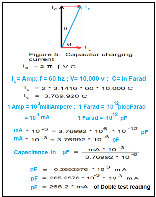
Capacitance (pF) =
test data in mA x 265
Remember capacitance measurement is in picoFarad and it is directly proportional to test data in mA.
A transformer that suffered deformation on its windings and core geometry due to internal fault will usually show downward trending of picoFarad reading value.
Capacitance Downward Trend

A perfect insulator or capacitor has a power factor reading of 0 % (% P.F = 0 ) as shown by mathematical computation but not in real world application.
Try a simulation by increasing the total charging current It = 70 mA, or until the power factor reading is 0.0851 %. You will notice that you will get a very high capacitance reading value = 18,550 picoFarad ( pF ) and also confirming the mathematical computation of a perfect insulator or capacitor has a power factor reading of approximately equal to zero ( 0 ) % P.F.
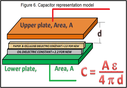
Assuming you have a baseline capacitance value of your transformer during factory test and your historical capacitance reading is trending downward meaning picoFarad value is going down. Therefore it is a warning indicator that internal damage in winding or core is possible. It is also an indicator that the paper and oil insulation properties is deteriorating because the value of its dielectric constant is no longer the same. For new insulation dielectric constant of paper = 2 and for oil = 2.2
Memory recall capacitance formula = ( Area * dielectric constant )/ (12.57 * distance between plates).
Looking at the formula it is easy to see that deteriorating oil and paper means lowering its dielectric constant and it is directly proportional to the capacitance value. Hence a downward trend of capacitance reading means an indicator of paper and oil dielectric constant breakdown.
A strong impact during delivery of transformer to a site location enough to deform the internal geometry of a transformer will also exhibit a downward trending in capacitance reading value. Again looking at the capacitance formula, the plate area of capacitor referring to representation model might shrink or deformed due to a large gravitational force during installation or due to a large acceleration force during delivery and hence lowering the calculated value of Area. Since Area is directly proportional to capacitance value any reduction in Area will be captured by the downward trending of the capacitance reading.
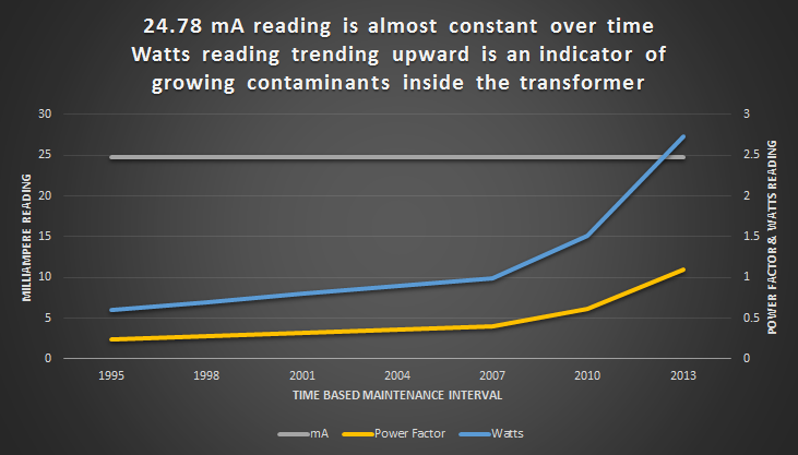
A transformer that has lots of contaminants on its insulating oil and paper will usually show an increasing trend of watts reading value and also increasing power factor (%) reading. Example of contaminants to oil and papers are moisture, arcing byproducts and metallic particles from forced oil motors. Most probably the contaminants are water or moisture due to gasket leaks.
To emphasize even if the charging mA current is rated in good condition meaning almost constant the percentage change is 0 - 3% . But if the power factor is continue to trend upward, it means the transformer is getting wet due to gasket leaks or more resistive contaminant to oil such as arcing byproducts or thermal fault byproduct o metallic particles from forced oil motors.
| Baseline mA | Range | % Change | Rating |
| 24.78 mA | 24.79 - 25.52 mA | 0 - 3% | Good |
| 24.78 mA | 25.65 - 26.0 mA | 3.5 - 5 % | Deteriorated |
| 24.78 mA | 26.14 - 27.26 mA | 5.5 - 10% | Investigate |
| 24.78 mA | 27.38 mA and above | Above 10% | Bad |
Watts trending upward
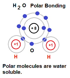
Moisture or water is known as polar (molecule) contaminants referring to chemical definition of polar molecule. Polar molecules can be easily understood by drawing its atomic outer orbit. When electron in outer orbit are shared by another atom we say polar bonding happen (hence called polar molecule). Why this knowledge is important in oil contamination analysis? As you can see there are 6 more free electrons from the oxygen atom that can be attracted by copper atoms in winding, iron atom in lamination, and steel plate frame support. Remember oxidation is loss of electrons.The drawing below is helpful to see that oxygen molecules is the source of that loss of electrons.
To prevent the copper atoms and iron atom to attract the free electrons from oxygen we add inhibitor in our oil. What it does is the free electrons from oxygen will bond first on these inhibitor therefore preventing it to bond on copper winding, laminated steel sheet and steel frame support. So next time you read your oxygen report from DGA analysis try to see also your required inhibitor to protect your copper winding, iron steel plates and lamination from oxidation.
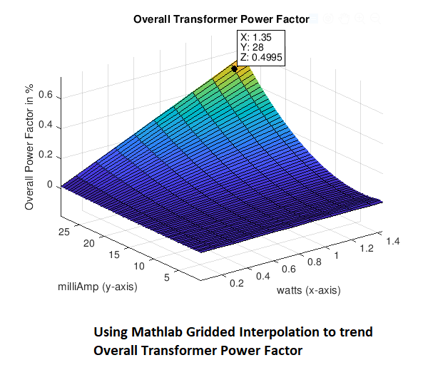
Try a simulation by increasing the wattage reading using the above calculator and you will see the increase of power factor (P.F.) reading as wattage reading is increased.
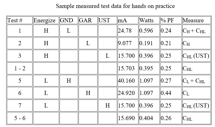
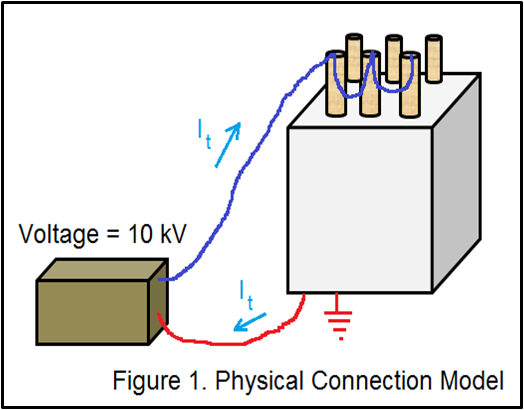
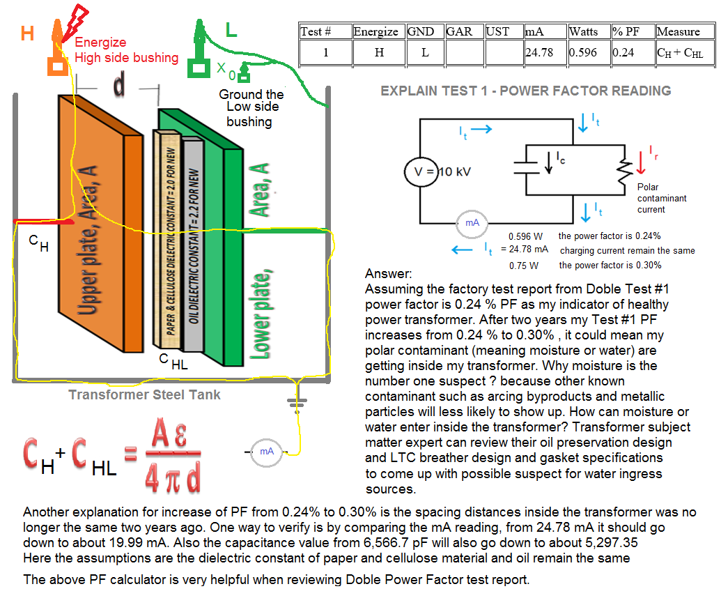
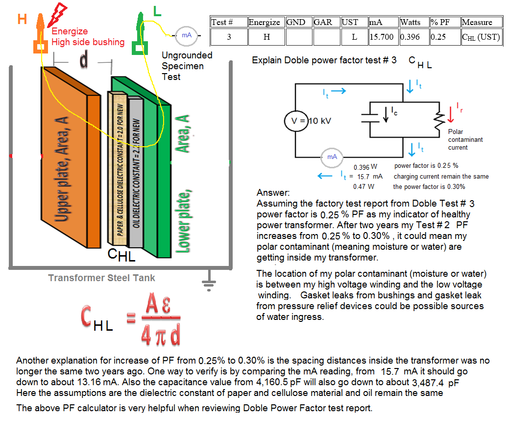
In a perfect insulator or capacitor, electrical current cannot actually flow through between two conductive plates because the dielectric material between two plates would not allow it. But due to contaminants there is an internal leakage current flowing between plates through these contaminants. These contaminants are due to moisture ingress inside the main tank of a transformer because of worn out gaskets in bushings and other gasketed interface connection, arcing byproducts, and metallic particles. Doble Test #2. (CH) and Doble Test #6 (CL) are example of these insulator or capacitor. Test #2 CH - INSULATION testing is about measuring the total leakage current flowing through contaminants between the high voltage winding as plate #1 and grounded tank is the plate # 2 . The dielectric materials between the two capacitor plates model are the thermally upgraded kraft papers used to cover each rectangular high voltage winding conductor plus the insulating oil. The possible contaminants are moisture, arcing byproduct and metallic particles that can be absorbed by kraft papers and oil.
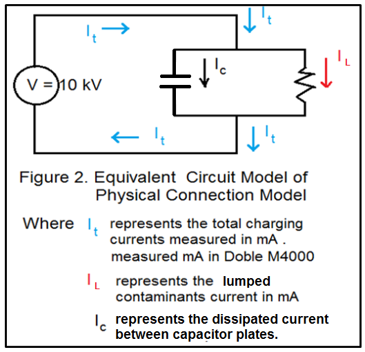
During Overall Test of power transformer using Doble M4000 series test instrument the H1-H2-H3 bushings are shorted and are energized by 10 kV voltage source and there is a safe leakage current flowing through these contaminant and return to the ground. The value of these safe leakage current is in mA. Refer to Figure 1 , Figure 2 and sample test data for Test #2, the total leakage current is 9.077 mA.


Credit: Doble Engineering
Formula Recall: (%)PF = (test data in watts x 10) / test data in mA
Formula Recall: Capacitance (in picoFarad) = test data in mA x 265


to use the calculator